File list
This special page shows all uploaded files.
First page |
Previous page |
Next page |
Last page |
| Date | Name | Thumbnail | Size | Description | Versions |
|---|---|---|---|---|---|
| 14:13, 19 June 2017 | Potentiometer.png (file) |  |
10 KB | A picture of the schematic of the potentiometer | 1 |
| 10:51, 19 June 2017 | Rendering assem.jpg (file) |  |
122 KB | final rendering | 3 |
| 10:41, 19 June 2017 | Output.jpg (file) |  |
125 KB | The output schematic | 1 |
| 09:52, 19 June 2017 | Output block.jpg (file) | 124 KB | A schematic of the output block | 1 | |
| 09:50, 19 June 2017 | Stop belt.jpg (file) |  |
106 KB | A schematic of the system that stops the belt | 1 |
| 09:35, 19 June 2017 | Lane selection system 1.jpg (file) |  |
80 KB | Lane selection system 1 | 1 |
| 09:31, 19 June 2017 | Lane selection system.jpg (file) |  |
94 KB | The schematic of the lane selection system | 1 |
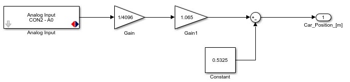
| 09:29, 19 June 2017 | Car position.jpg (file) | 35 KB | The schematic of the carposition | 1 | |
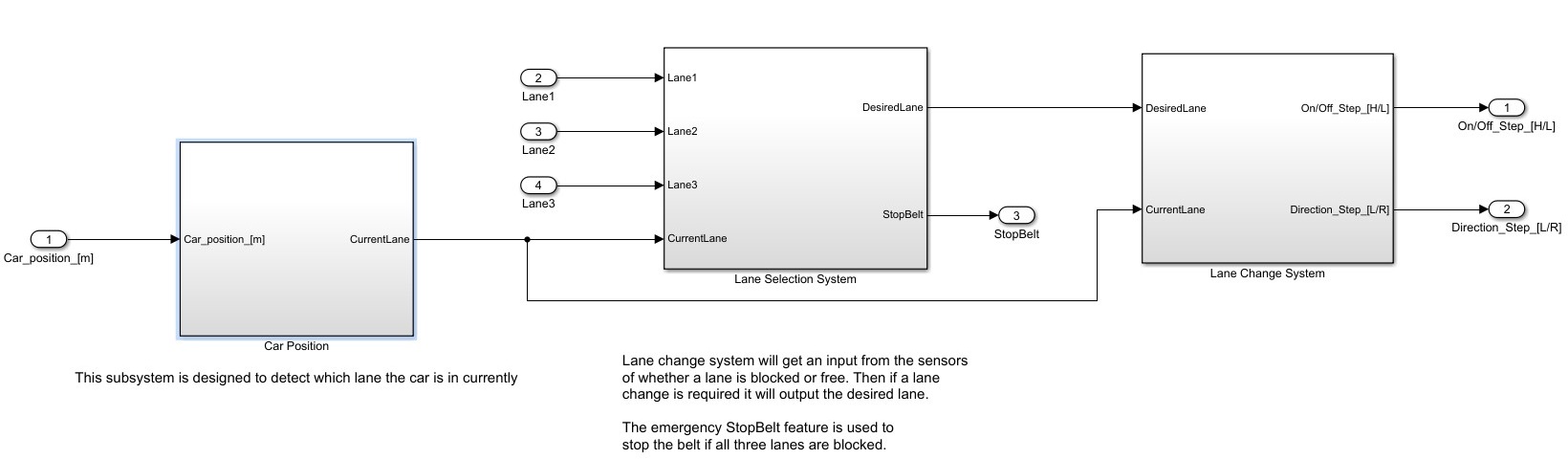
| 09:03, 19 June 2017 | Main algorithm.jpg (file) |  |
86 KB | Schematic main algorithm | 1 |
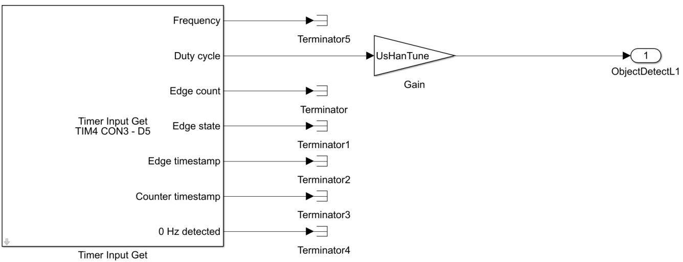
| 08:58, 19 June 2017 | Ultrasonic sensor software.jpg (file) |  |
63 KB | Schematic ultrasonic sensor | 1 |
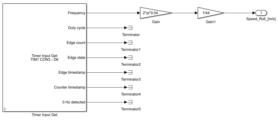
| 08:56, 19 June 2017 | Speed sensor.jpg (file) |  |
54 KB | Schematic speed sensor | 1 |
| 08:54, 19 June 2017 | Position sensor.jpg (file) | 16 KB | Schematic of the position sensor | 1 | |
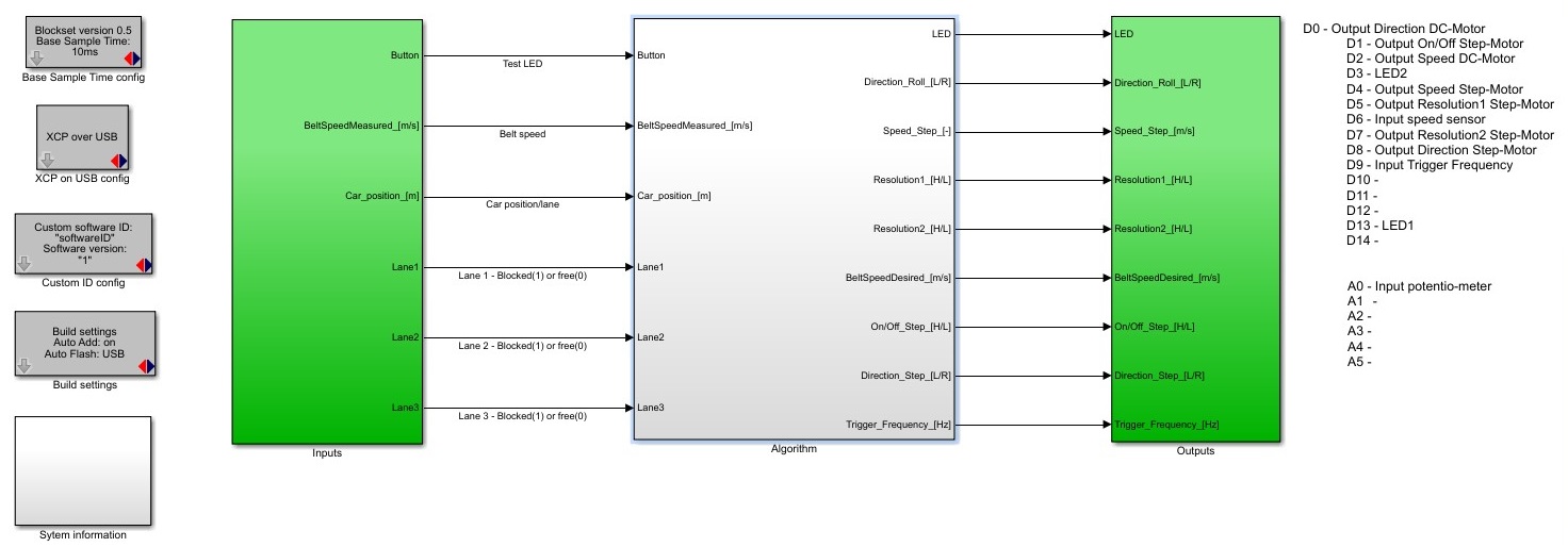
| 08:37, 19 June 2017 | Complete software.jpg (file) |  |
120 KB | A complete lay out of the software | 1 |
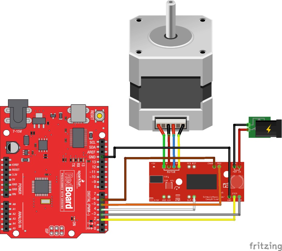
| 07:02, 19 June 2017 | Microcontroler.jpg (file) |  |
115 KB | A picture of the microcontroller with the wires | 1 |
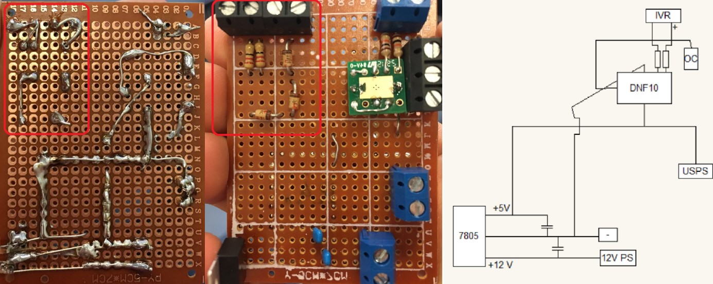
| 06:52, 19 June 2017 | Low voltage circuit.jpg (file) |  |
203 KB | This is a picture of the frequency filter with schematics | 1 |
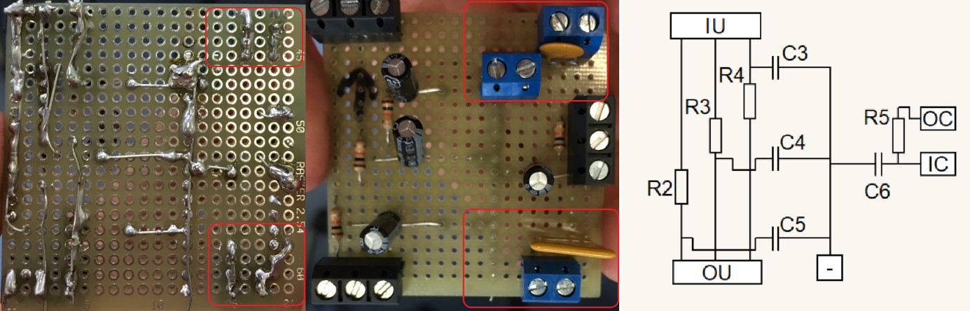
| 06:43, 19 June 2017 | High frequency filter.jpg (file) |  |
151 KB | A picture of the High frequency filters PCB with schematics | 1 |
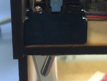
| 19:54, 8 June 2017 | The switch.jpg (file) |  |
18 KB | A picture of the swicht build in the bridge | 1 |
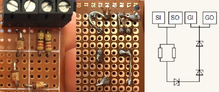
| 19:49, 8 June 2017 | Zenerdiode.jpg (file) |  |
72 KB | A picture of the PCB of the zenerdiode en the electric schemetic | 1 |
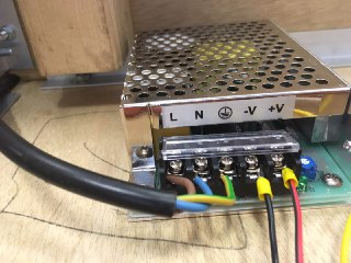
| 19:30, 7 June 2017 | Transformer.png (file) | 195 KB | A picture of the transformer | 1 | |
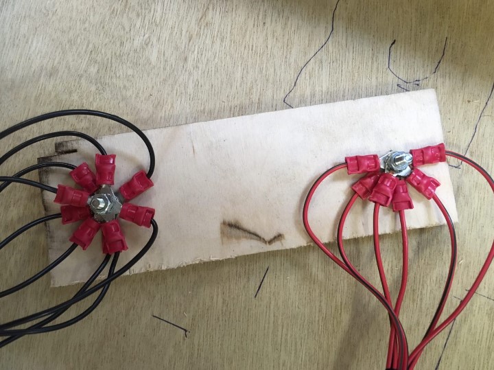
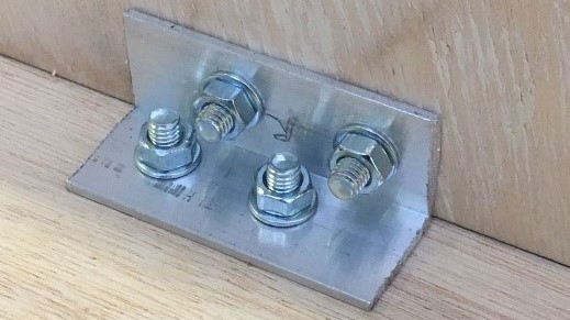
| 19:06, 7 June 2017 | Ground and source star.jpg (file) |  |
110 KB | A picture of the stars with the mounting plate | 1 |
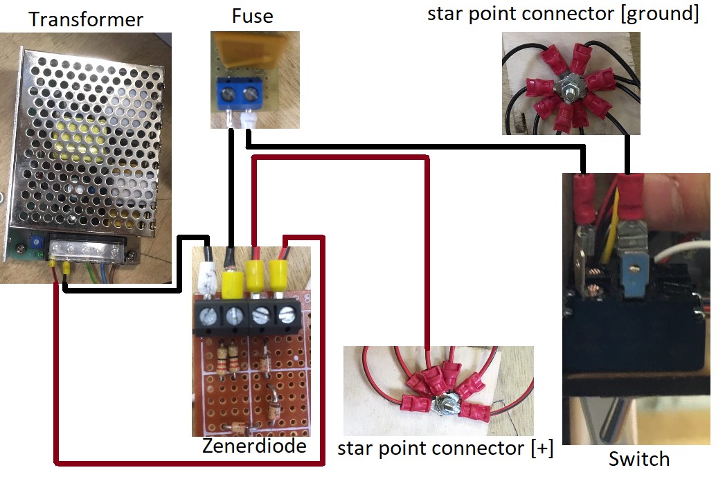
| 19:04, 7 June 2017 | Connection diagram.jpg (file) |  |
153 KB | Connection diagram | 1 |
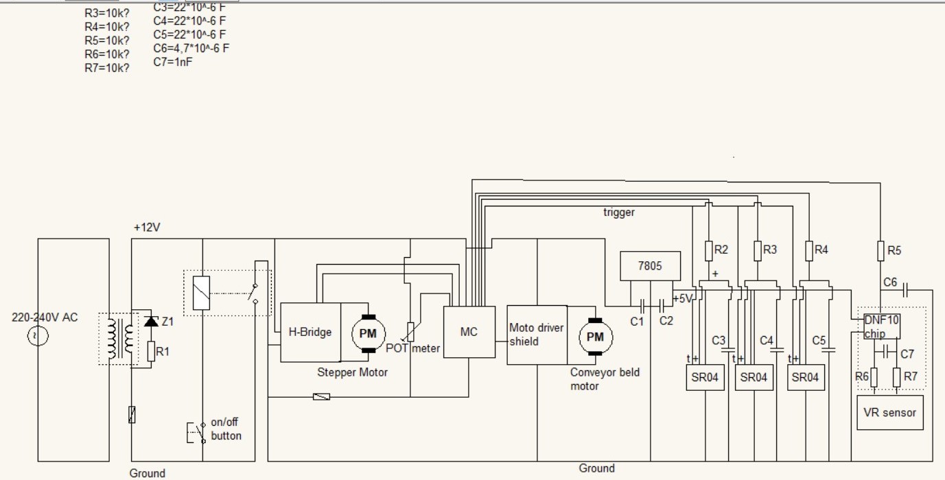
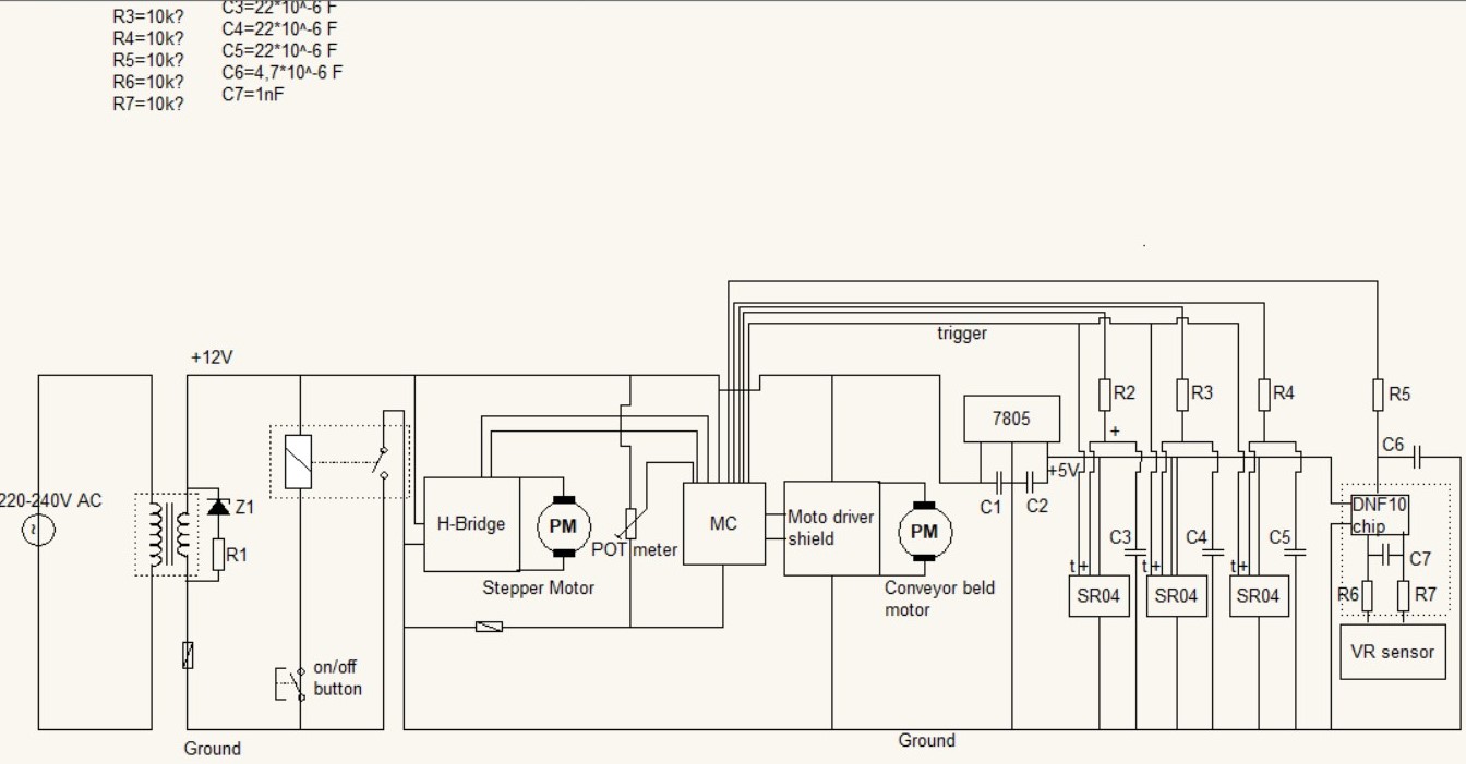
| 18:46, 7 June 2017 | Electric scheme.jpg (file) |  |
128 KB | The complete electric scheme | 1 |
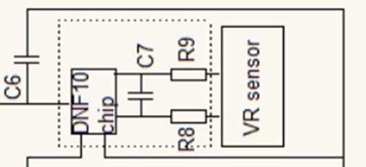
| 14:01, 7 June 2017 | VR sensor.jpg (file) |  |
44 KB | This picture zooms in on the vr sensor | 1 |
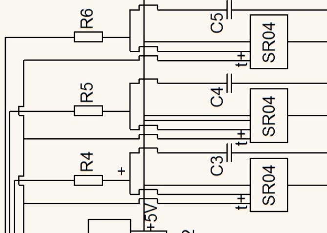
| 13:04, 7 June 2017 | Ultrasonic sensors.jpg (file) |  |
74 KB | This picture zooms in to the ultrasonic sensors | 1 |
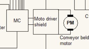
| 13:00, 7 June 2017 | Conveyerbelt motor.jpg (file) |  |
33 KB | This picture zooms in on the conveyerbelt motor | 1 |
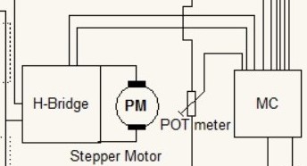
| 12:57, 7 June 2017 | Steppermotor.jpg (file) |  |
38 KB | This picture zooms in to the steppermotor | 1 |
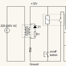
| 12:50, 7 June 2017 | Switch.jpg (file) |  |
39 KB | This picture zooms in on the switch of the electric scheme | 1 |
| 12:37, 7 June 2017 | The electric circuit.jpg (file) |  |
131 KB | A picture of the whole electric circuit | 1 |
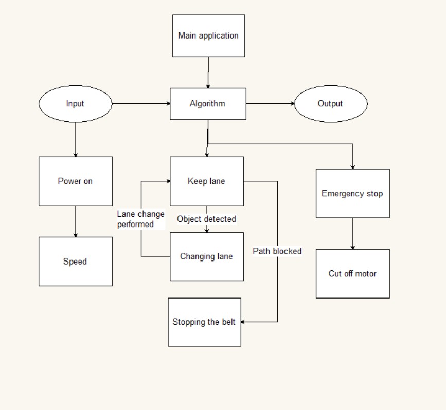
| 11:11, 7 June 2017 | Software diagram.jpg (file) |  |
50 KB | Software diagram | 1 |
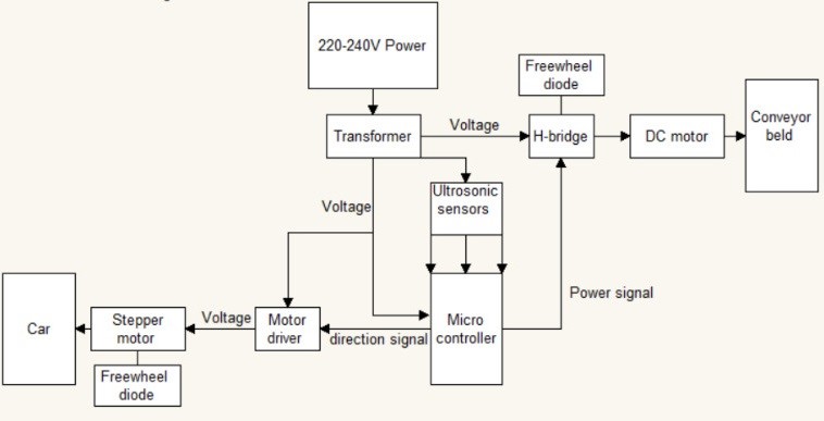
| 11:10, 7 June 2017 | Electric diagram.jpg (file) |  |
32 KB | Electric diagram | 1 |
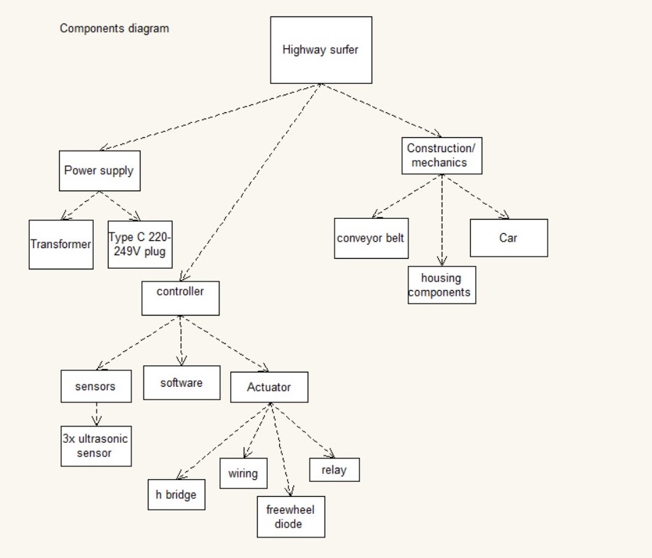
| 11:09, 7 June 2017 | Components diagram.jpg (file) |  |
87 KB | components diagram | 1 |
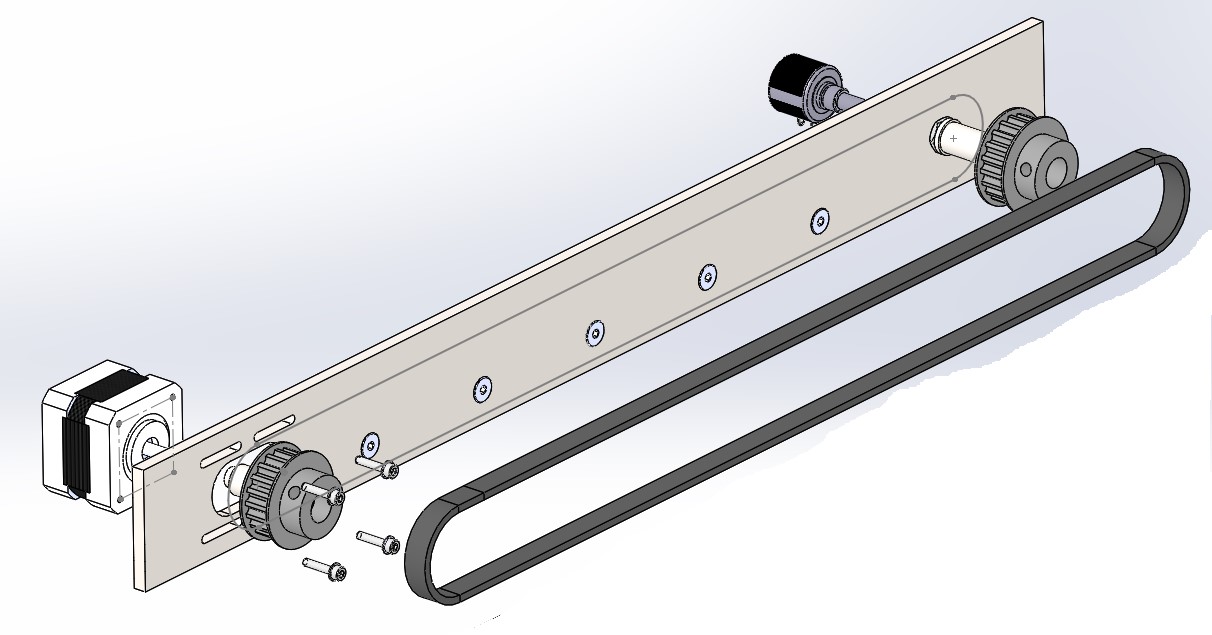
| 09:13, 7 June 2017 | Exploded view lane change mechanism.jpg (file) |  |
101 KB | The exploded view of the lane change machanism | 1 |
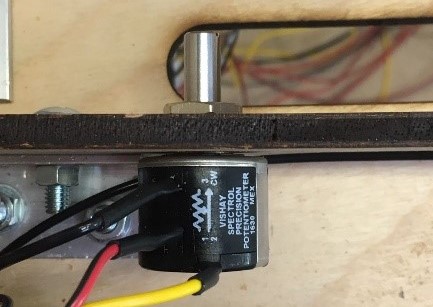
| 09:10, 7 June 2017 | Top view potentiometer.jpg (file) |  |
61 KB | The top view of the potentiometer mounted to the bracket | 1 |
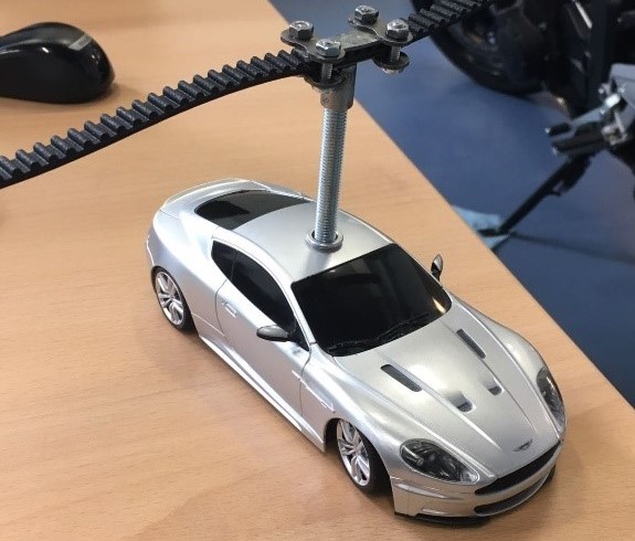
| 09:08, 7 June 2017 | Treaded bushing.jpg (file) |  |
82 KB | The treaded bushing to mount the car on | 1 |
| 09:07, 7 June 2017 | Lane change mechanism bracket.jpg (file) |  |
72 KB | The bracket where the motor and the pot meter is mounted | 1 |
| 09:06, 7 June 2017 | Car construction.jpg (file) |  |
92 KB | Total car construction | 1 |
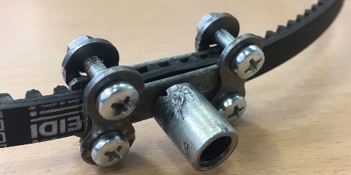
| 09:05, 7 June 2017 | Assembelt belt-clamp.jpg (file) |  |
57 KB | The whole belt clamp assembelt | 1 |
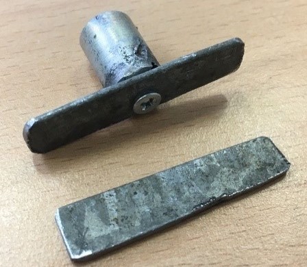
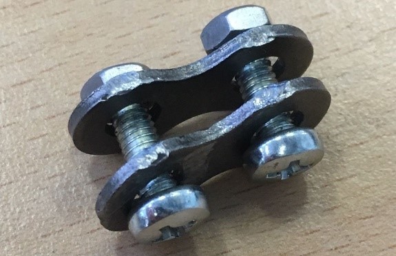
| 09:03, 7 June 2017 | Chain link clamps.jpg (file) |  |
84 KB | The clamps for the belt | 1 |
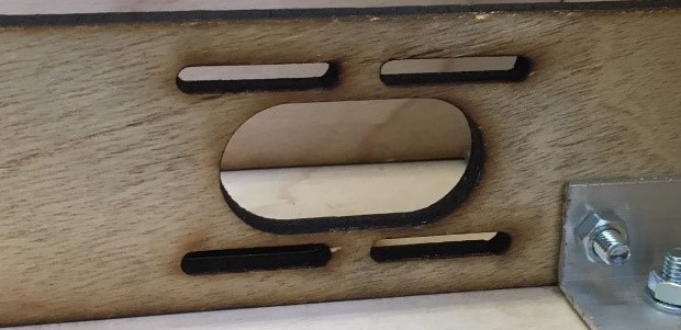
| 08:36, 7 June 2017 | Bridge cover assembly.png (file) |  |
85 KB | The picture is cropt | 2 |
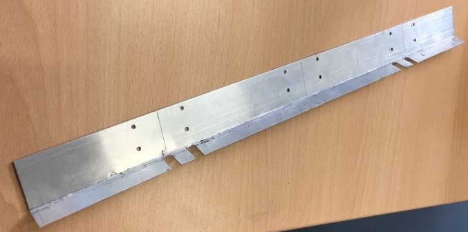
| 08:34, 7 June 2017 | 20x20 profile.jpg (file) |  |
66 KB | The picture is cropt | 2 |
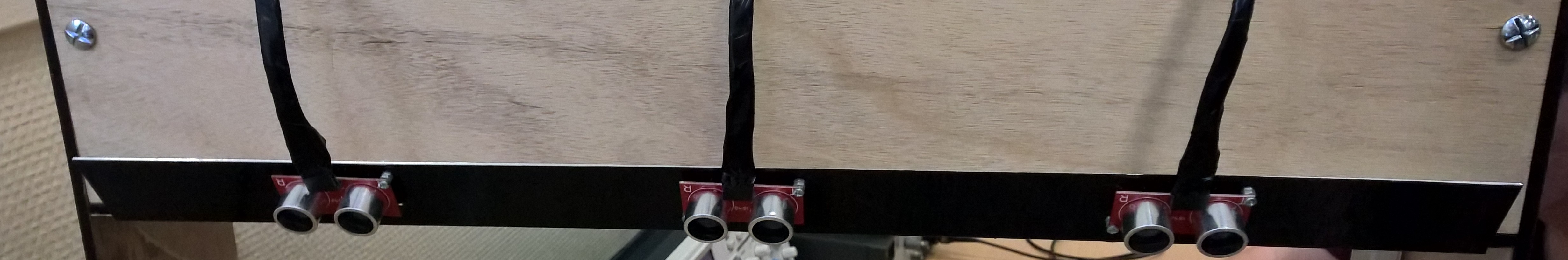
| 08:00, 7 June 2017 | Ultrasonic sensor bracket complete.jpg (file) | 672 KB | The ultrasonic sensor bracket complete with the sensors en cables | 1 | |
| 19:35, 6 June 2017 | Ultrasonic sensor bracket.jpg (file) |  |
74 KB | The bracket for the ultrasonic sensors | 1 |
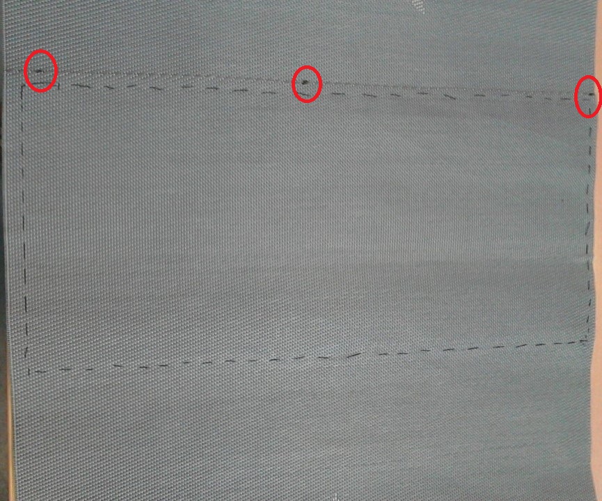
| 19:10, 6 June 2017 | Conveyerbelt.jpg (file) |  |
266 KB | Added the markings | 2 |
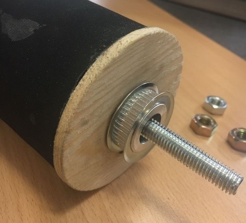
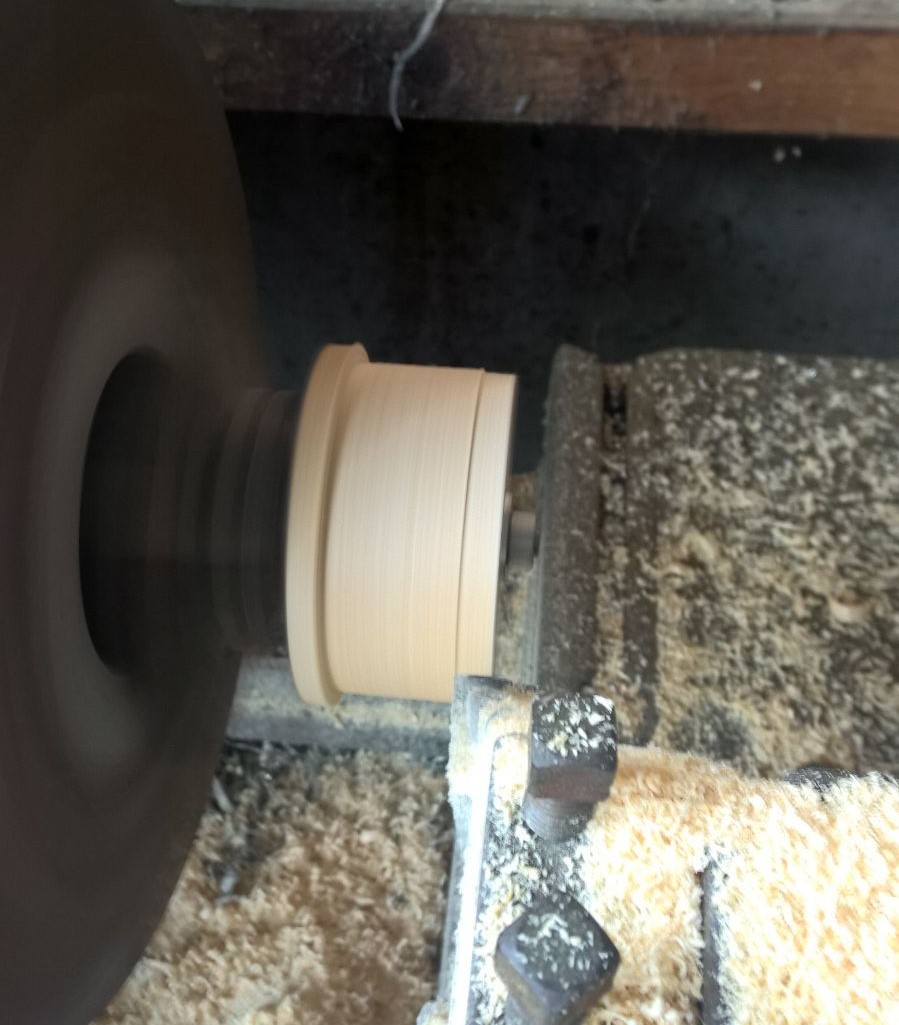
| 14:17, 31 May 2017 | Roller-end for powered side.jpg (file) |  |
77 KB | Shows the assembly of the powered side of the roller | 1 |
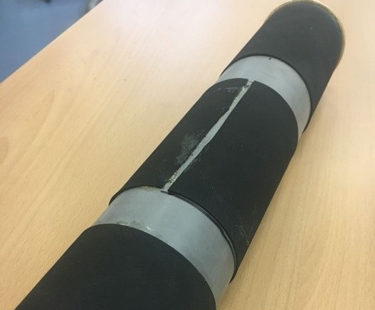
| 14:14, 31 May 2017 | PVC EPDM.jpg (file) |  |
60 KB | The PVC roller with the EPDM glued to it for grip | 1 |
| 13:40, 31 May 2017 | Bearingblock machining.jpg (file) |  |
161 KB | Shows the machining of the bearing blocks | 1 |
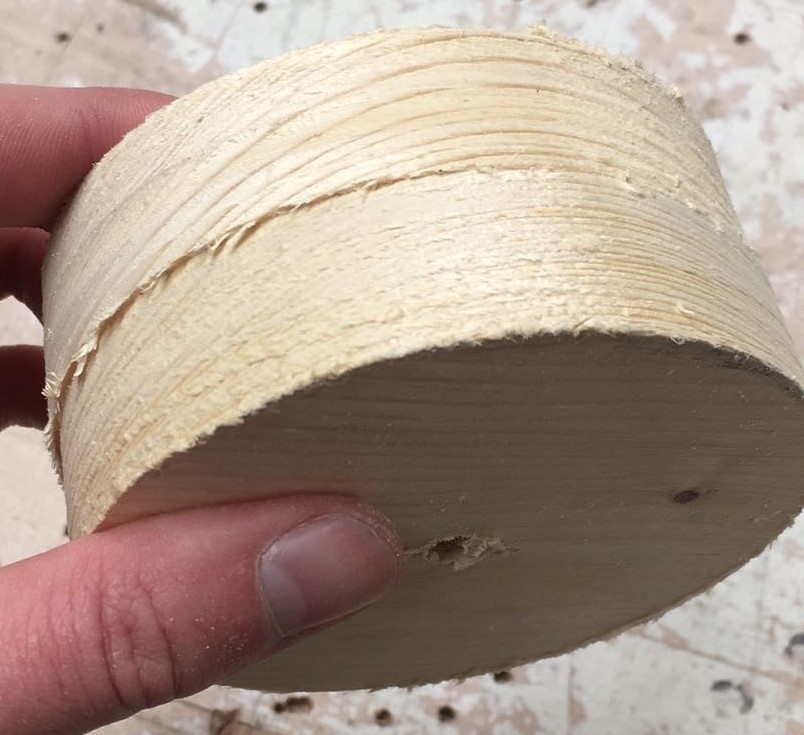
| 13:38, 31 May 2017 | Bearingblock unmachined.jpg (file) |  |
135 KB | This picture displays the unmachined bearing block | 1 |
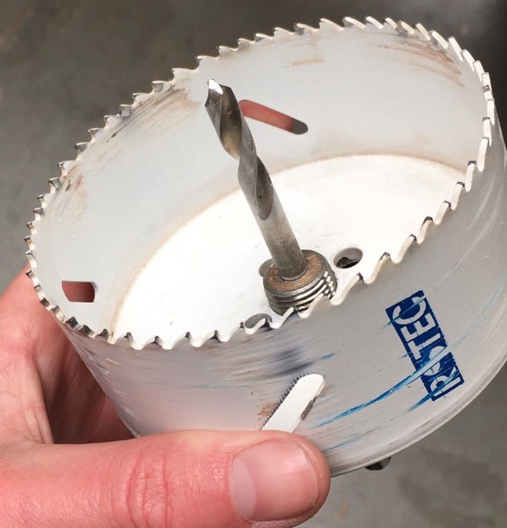
| 13:37, 31 May 2017 | Drill for roller-blocks.jpg (file) |  |
115 KB | This picture displays the drill used to make the bearing blocks | 1 |
| 09:53, 31 May 2017 | Exploded view roller tensioning side.jpg (file) |  |
95 KB | An exploded view of the roller on the tensioning side of the belt | 1 |
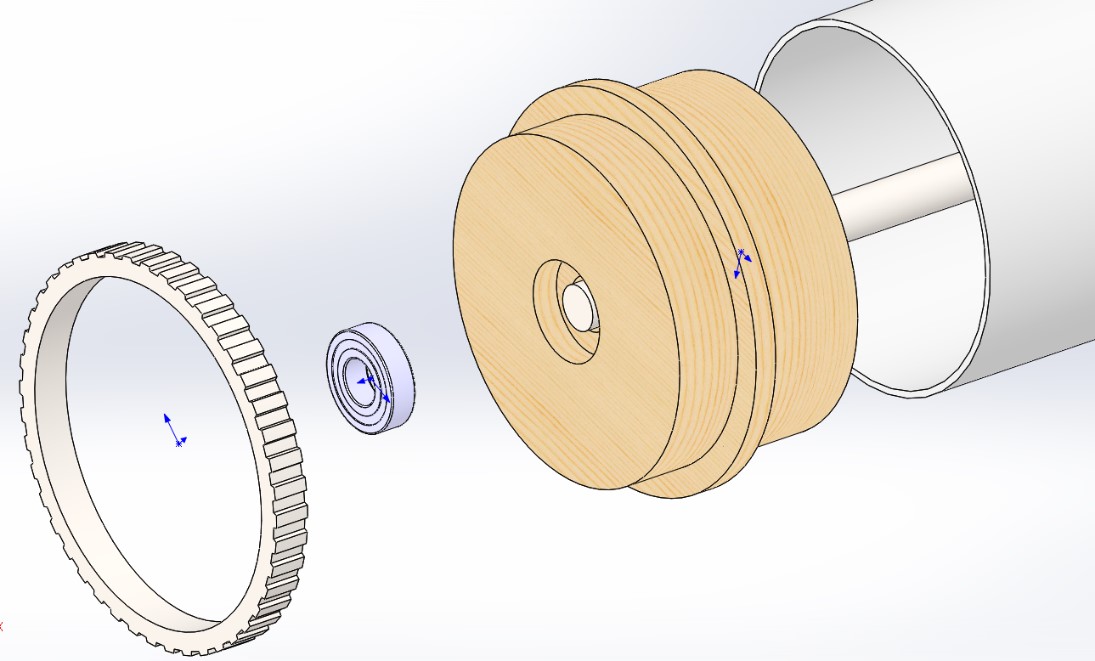
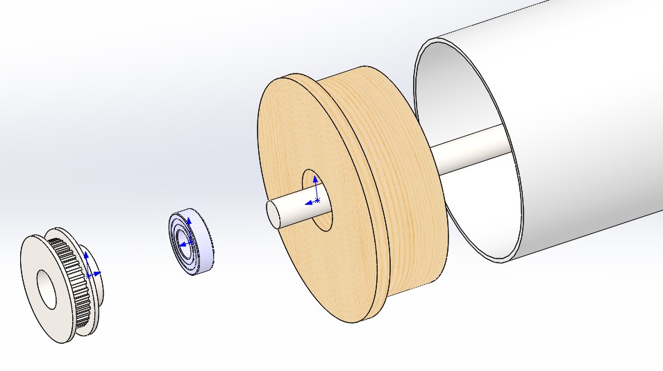
| 09:53, 31 May 2017 | Exploded view roller powerd side.jpg (file) |  |
60 KB | An exploded view of the roller on the powered side | 1 |
First page |
Previous page |
Next page |
Last page |