Difference between revisions of "HANcoder/STM32/Blocks/Timer Input Get"
| Line 5: | Line 5: | ||
Reads the information from a timer input pin. | Reads the information from a timer input pin. | ||
| + | |blockImage = TimerInputGet.png | ||
| + | |maskImage = TimerInputGetMask.png | ||
| − | + | |TimerInputPin = Selects the timer input pin. | |
| + | |ZeroHzDetectionTime = Determines after how many milliseconds since the last edge the 0 Hz detected output flag should go high. | ||
| + | |SampleTime = Default | ||
| − | + | |SeeAlso = [[HANcoder/Timer_Input_IRQ|Timer Input IRQ]], [[HANcoder/Quadrature_Encoder_Get|Quadrature Encoder Get]] | |
| − | + | }} | |
| + | == Inputs (inports) == | ||
| + | reset input (optional) if the value goes from 0 to 1 the counter output will be reset. | ||
| − | Duty cycle | + | == Outputs(Outports) == |
| − | + | Output 1:Frequency: The last measured frequency on the pin in Hz. | |
| − | The last measured duty cycle on the pin as a % with a scaling factor of 100 for | + | Output 2:Duty cycle: The last measured duty cycle on the pin as a % with a scaling factor of 100 for |
improved resolution. So 5000 = 50% for example. | improved resolution. So 5000 = 50% for example. | ||
| − | + | Output 3:Edge count: The number of edges that were detected on the input pin since startup. | |
| − | + | Output 4:Edge timestamp: A 32-bit timestamp value of the last edge. The timestamp is derived from an | |
| − | Edge count | ||
| − | |||
| − | The number of edges that were detected on the input pin since startup. | ||
| − | |||
| − | |||
| − | Edge timestamp | ||
| − | |||
| − | A 32-bit timestamp value of the last edge. The timestamp is derived from an | ||
internal 32-bit free running counter that runs at 24 Mhz. | internal 32-bit free running counter that runs at 24 Mhz. | ||
| − | + | Output 5:0 Hz detected: A boolean flag that will go high if no edges were detected for the time specified | |
| − | |||
| − | 0 Hz detected | ||
| − | |||
| − | A boolean flag that will go high if no edges were detected for the time specified | ||
as the zero Hz detection time. Upon the next edge the flag will go low again. | as the zero Hz detection time. Upon the next edge the flag will go low again. | ||
| + | == Block parameters == | ||
| + | {| class="wikitable" | ||
| + | |- | ||
| + | ! style="width:150px" | Parameter | ||
| + | ! Description | ||
| + | |- | ||
| + | | Quad encoder module | ||
| + | | Select the output pin where the PWM signal should be generated. | ||
| + | |- | ||
| + | | Configuration | ||
| + | | Select the pin electrical configuration. | ||
| + | |- | ||
| + | | Show counter reset input | ||
| + | | When this checkbox is ticked an input appears. | ||
| + | |- | ||
| + | | Sample time | ||
| + | | Sample time of the block. The Sample time (in seconds) defines the rate at which the block is visited by the real-time scheduler of the target. The value of the Sample time has to be an integer multiple of the base sample time of the model. | ||
| + | |} | ||
| − | + | == Examples == | |
| − | + | [[HANcoder/Examples/Workshop?| Workshop]] | |
| − | |||
| − | |||
| − | |||
| − | |||
| − | |||
| − | |||
| − | |||
| + | {{HANcoder/BlockFooter| | ||
| + | |SeeAlso = [[HANcoder/PWM_Init|PWM Init]] | ||
}} | }} | ||
Revision as of 14:55, 27 April 2017
Supported Targets: Olimexino, E407, P405
Contents
General information about Timer Input Get
Reads the information from a timer input pin.
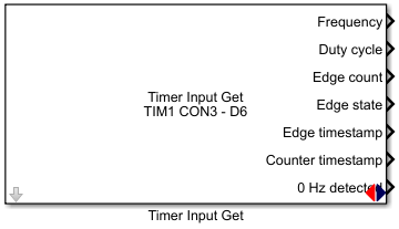
Block
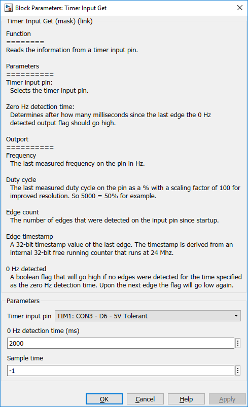
Mask
Inputs (inports)
reset input (optional) if the value goes from 0 to 1 the counter output will be reset.
Outputs(Outports)
Output 1:Frequency: The last measured frequency on the pin in Hz. Output 2:Duty cycle: The last measured duty cycle on the pin as a % with a scaling factor of 100 for improved resolution. So 5000 = 50% for example. Output 3:Edge count: The number of edges that were detected on the input pin since startup. Output 4:Edge timestamp: A 32-bit timestamp value of the last edge. The timestamp is derived from an internal 32-bit free running counter that runs at 24 Mhz. Output 5:0 Hz detected: A boolean flag that will go high if no edges were detected for the time specified as the zero Hz detection time. Upon the next edge the flag will go low again.
Block parameters
| Parameter | Description |
|---|---|
| Quad encoder module | Select the output pin where the PWM signal should be generated. |
| Configuration | Select the pin electrical configuration. |
| Show counter reset input | When this checkbox is ticked an input appears. |
| Sample time | Sample time of the block. The Sample time (in seconds) defines the rate at which the block is visited by the real-time scheduler of the target. The value of the Sample time has to be an integer multiple of the base sample time of the model. |

