Difference between revisions of "Testing the project"
From OpenMBD
| Line 3: | Line 3: | ||
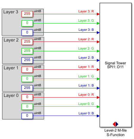
[[File:example_usage.PNG]] | [[File:example_usage.PNG]] | ||
*Build the model | *Build the model | ||
| − | *The Diagnostic Viewer indicates that the build process completed successfully. If not | + | *The Diagnostic Viewer indicates that the build process completed successfully. If not, the errors must be resolved. A common mistake is an incorrect spelling of variable names or function names. |
*Test the generated application by programming the Olimexino STM32 board with the signal tower connected to 5V, GND, and D11 (if SPI1 was selected) or D34 (if SPI2 was selected). | *Test the generated application by programming the Olimexino STM32 board with the signal tower connected to 5V, GND, and D11 (if SPI1 was selected) or D34 (if SPI2 was selected). | ||
---- | ---- | ||
Part 4: [[Updating the build environment]] - '''Previous''' | Part 4: [[Updating the build environment]] - '''Previous''' | ||
Latest revision as of 14:03, 1 March 2019
Finally, the new block can be tested.
- Create a Simulink model that provides inputs for the twelve input ports, such as depicted below:
- Build the model
- The Diagnostic Viewer indicates that the build process completed successfully. If not, the errors must be resolved. A common mistake is an incorrect spelling of variable names or function names.
- Test the generated application by programming the Olimexino STM32 board with the signal tower connected to 5V, GND, and D11 (if SPI1 was selected) or D34 (if SPI2 was selected).
Part 4: Updating the build environment - Previous
