Problems and Solutions (FAQ)
This page is dedicated to problems which have occurred during the first stages of using SIMarchitect and their possible solutions. This page will be updated as development continues.
Contents
Parameter Files
This chapter will list frequently occurring problems with Parameter Files and their solutions.
Parameter files:
- First segment is used to define the values of parameters.
- Second segment (Connection Information) is used to describe connector information and the respective unit.
- When the directory of the model is changed, the parameterfile location must be redefined.
- When a components is copied, the parameterfile must be redefined.
- Parameter files can only be assigned to 'Module' components and not 'Area' components. (Signals to and from Bus)
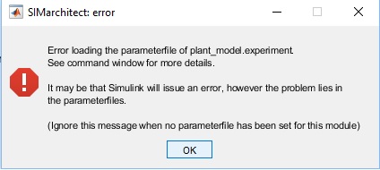
Problem: SIMarchitect returns an error loading the parameterfiles. (Shown below)
Solution: There is an error in the parameterfile code. Check the code inside the MATLAB editor. The Command Windows or Diagnostics Viewer may show more information about the source of the error.
Problem: One of the defined parameters is not being read in SIMarchitect.
Solution: Some functions are not usable within parameterfiles. Run the parameterfile separately inside MATLAB and check the desired value is created in workspace. If not, the definition of the parameter is incorrect.
Signals To and From Bus
This chapter will list frequently occurring problems with Bus signals and their solutions.
Module
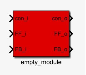
The following is valid for the 'Module' sub-components. This type of component is seen below.
Bus Signals:
- The signals are sent to the bus inside each component block by the 'Bus Creator'. For these signals use a 'From' block. Name the signal lines to the Bus creator to use these names inside the bus.
- The signals selected using the 'Bus Selector' are sent into the component in mux form. These signals must be split using a demux block (not a bus selector). Each signal is then sent to a 'Goto' block with the name of the respective variable. Pay attention to dimension the signals correctly when using demux.
Dimension Signals in Demux
To dimension signals properly in a demux block, follow the steps below. This is only applicable when signals with a dimension larger than 1 are used.
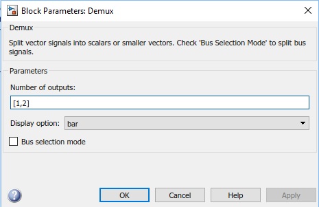
The figure below shows the properties of a demux where the first signal has dimension 1 and the second signal a dimension 2. The dimensions are to be defined using an array of the sizes. For this figure, this is [1,2].
This method is applicable to all dimensions and sizing. If this step is not taken for multi-dimensional signals, the dimensions will, most likely, be misplaced and the results will be incorrect.
Area
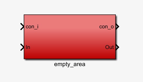
The following is valid for the 'Area' sub-components. This type of component is seen below.
Bus Signals:
- The signals are sent to the bus inside each component block by the 'Bus Creator'. For these signals use a 'From' block. Name the signal lines to the Bus creator to use these names inside the bus.
- The signals are sent into the component as a bus signal. Inside the component, use a 'Bus selector' to select the required signals. Each signal is then sent to a 'Goto' block with the name of the respective variable.
Goto and From tags
The structure of SIMarchitect uses 'goto' and 'from' tags to distribute information within the model. Things to remember about these tags:
- 'From' tags cannot pass virtual boundaries within a model. (CHECK)
- 'Goto' tags can be set to 'local', 'scoped' or 'global'. The preference inside these model-types is to use local. This way, the model stays organised and understandable. Furthermore, signals using a global goto block are not sent using the bus structure, which is undesirable.
Other
This chapter contains other problems that users may encounter and their solutions.
Problem: MATLAB crashes when a block is copied and pasted.
Solution: Copy and paste only the component and not the 'Goto' and 'From' blocks connected to the module. So, only the blue area must be copied.
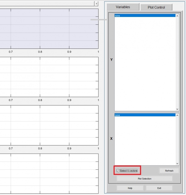
Problem: Plotting graphs using an alternative x-axis to time in the Results Plot GUI.
Solution: The standard x-axis for the Results Plot GUI is time. To change this, check the 'select x-vectors' box and select the desired x-axis value with the corresponding y-axis value.
